


LLegoLLaS
-
Posts
2060 -
Joined
-
Last visited
-
Days Won
11
Posts posted by LLegoLLaS
-
-
Sent PM's.
Still open to offers;
-
Long story short:
Am nevoie de un PCB care a fi legat la 14volti si care are pe el un step-down pentru alimentarea unui PIC (PIC16 sau PIC18) + LIS3DH (accelerometru)
Pentru detalii, pe privat sau discord;
Am nevoie de proiect complet, gerber si cunostinte de electronica intrucat am nevoie de identificare/stabilire piese in afara de cele doua componente principale (PIC si LIS3DH care raman stabilite) - in special tranzistori potriviti pentru step-down/up whatever -
RST Note: Am scurtat articolul, am postat doar ce e relevant pentru a-l construi; puteti citi intregul articol la sursa;
Pentru componente am scos linkurile, ele se pot gasi pe orice site din RO (ardushop,cleste,optimusdigital,digikey etc) la pret mic;
Abstract
In this project, the idea of the adaptive brake light was reinterpreted using an Arduino Nano (ATMEGA328P) microcontroller. With a transistor as switching unit and an acceleration or GPS sensor, the components are connected in between the braking signal – only one additional power cable needs to be pulled. Any vehicle type can be easily retrofitted in this way without complicated wiring or the need to detect pedal force. The code was programmed using existing Arduino libraries, the cases were 3D printed and the finished modules were tested in practice. The total price of required components does not exceed $15.Materials & Methods
Components
Microcontroller: ATMEGA328P (Arduino Nano Clone) (15 lei)
Accelleration-sensor: GY-521 MPU-6050 (15-30 de lei)
GPS-sensor: GY-NEO6MV2 (¬50 de lei)
Transistor: BD139 Genuine ON Semiconductor NPN 1.5 A / 80 V To-126 ZBDE W0HW ($0.20) (Polarity here is C/E/B! Regular C/B/E polarity will of course work aswell)
LEDs: T10 COB-LED (optionale, pentru testare in ''laborator@ - leduri de masina)
Software
Autodesk Inventor Professional 2019 (Build: 265, Release: 2019.2) (optional)
Fritzing beta (Ver. 0.9.4 ) (optional)
Arduino IDE 1.8.10 (Board: Arduino Nano, Processor: ATmega328P, Programmer: AVRISP mkII)
Libraries for Arduino IDE:
– without GPS: Wire.h
– with GPS: Wire.h, SoftwareSerial.h, TinyGPS.h
Source code
The operating principle of the source code is based on an interruption of the light signal using the transistor. This means that without triggering the sketch (i.e. at slow speeds or only slight changes in acceleration) the current sent by the brake pedal is passed through the microcontroller to light up the brake lights. Only as soon as the acceleration sensor detects an acceleration above a defined threshold value and (if used) the GPS sensor detects a speed above a defined threshold value, the sketch is triggered and interrupts the continuous light signal for a defined time by the parameters BLINKON and BLINKOFF, resulting in a flashing effect. If the sketch is once activated, the flashing will then last for a defined STOPPINGTIME, independent of the currently read out data – so that, as in the example video, the flashing signal will last until the vehicle has come to a standstill or for a short time during the strong speed reduction in order to obtain the desired warning effect.
#include "Wire.h" #include "SoftwareSerial.h" #include "TinyGPS.h" #define STOPPINGTIME 1500 // in ms #define G_THRESHOLD 1.1 // activate above threshold #define G 2.7e8 // = 1 g #define BLINKON 75 // in ms #define BLINKOFF 75 // in ms #define INITFILT 400 // number of values averaged to get initial acceleration #define FILT 140 // number of values averaged to get current acceleration #define V_THRESHOLD 100 // in km/h #define MAXFAILEDGPSBYTES 1000 // number of bytes received from gps to abort without valid gps sequence #define MAXTIMESINCELASTFIX 2000 // in ms const int ledPin = 11; const int ledPin2 = 13; const int MPU_addr = 0x68; //I2C address const int GPSrxPin = 3; const int GPStxPin = 4; bool blinkStatus, ledStatus, risingEdge; unsigned long endTime, toggleTime; double gforce, oldforce; int16_t Xi, Yi, Zi; int32_t Xc = 0, Yc = 0, Zc = 0; double X, Y, Z, AccP; int16_t Xbuf[FILT] = {0}, Ybuf[FILT] = {0}, Zbuf[FILT] = {0}; int bufpos = 0, i; int32_t tmp; SoftwareSerial gpsSerial(GPSrxPin, GPStxPin); //rx (D3),tx (D4) for GPS TinyGPS gps; // create gps object float speed = 0; //vehicle speed in km/h long lat, lon; unsigned long fix_age; bool goodfix; void setup() { //Connect to G-Sensor Wire.begin(); Wire.beginTransmission(MPU_addr); Wire.write(0x6B); // PWR_MGMT_1 register Wire.write(0); // set to zero (wakes up the MPU-6050) Wire.endTransmission(true); Serial.begin(9600); // for USB monitor gpsSerial.begin(9600); // connect gps sensor for (i = 0; i<INITFILT; i++) { Wire.beginTransmission(MPU_addr); Wire.write(0x3B); // starting with register 0x3B (ACCEL_XOUT_H) Wire.endTransmission(false); Wire.requestFrom(MPU_addr,6,true); // request a total of 6 registers Xc+=Wire.read()<<8|Wire.read(); // 0x3B (ACCEL_XOUT_H) & 0x3C (ACCEL_XOUT_L) Yc+=Wire.read()<<8|Wire.read(); // 0x3D (ACCEL_YOUT_H) & 0x3E (ACCEL_YOUT_L) Zc+=Wire.read()<<8|Wire.read(); // 0x3F (ACCEL_ZOUT_H) & 0x40 (ACCEL_ZOUT_L) } Xc = Xc/FILT; Yc = Yc/FILT; Zc = Zc/FILT; pinMode(ledPin, OUTPUT); digitalWrite(ledPin, true); pinMode(ledPin2, OUTPUT); digitalWrite(ledPin2, true); blinkStatus = false; ledStatus = true; } void loop() { // GPS read i = 0; while(gpsSerial.available()) { //Data available? if(gps.encode(gpsSerial.read())) { //GPS telegram complete? speed = gps.f_speed_kmph(); break; // end while loop } if (i++ > MAXFAILEDGPSBYTES) // cancel after MAXFAILEDGPSBYTES bytes without valid telegram break; } //check for valid signal gps.get_position(&lat, &lon, &fix_age); goodfix = ((fix_age == TinyGPS::GPS_INVALID_AGE) || (fix_age > MAXTIMESINCELASTFIX)) ? false : true; //G-Sensor read Wire.beginTransmission(MPU_addr); Wire.write(0x3B); // starting with register 0x3B (ACCEL_XOUT_H) Wire.endTransmission(false); Wire.requestFrom(MPU_addr,6,true); // request a total of 6 registers Xbuf[bufpos]=Wire.read()<<8|Wire.read(); // 0x3B (ACCEL_XOUT_H) & 0x3C (ACCEL_XOUT_L) Ybuf[bufpos]=Wire.read()<<8|Wire.read(); // 0x3D (ACCEL_YOUT_H) & 0x3E (ACCEL_YOUT_L) Zbuf[bufpos]=Wire.read()<<8|Wire.read(); // 0x3F (ACCEL_ZOUT_H) & 0x40 (ACCEL_ZOUT_L) tmp = 0; for (i = 0; i<FILT; i++) { tmp += Xbuf[i]; } Xi = tmp; tmp = 0; for (i = 0; i<FILT; i++) { tmp += Ybuf[i]; } Yi = tmp; tmp = 0; for (i = 0; i<FILT; i++) { tmp += Zbuf[i]; } Zi = tmp; X = Yc*Zi - Zc*Yi; Y = Zc*Xi - Xc*Zi; Z = Xc*Yi - Yc*Xi; gforce = sqrt(X*X + Y*Y + Z*Z); Serial.print(G_THRESHOLD * G); Serial.print(','); Serial.print(8e8); Serial.print(','); Serial.print(G); Serial.print(','); Serial.println(gforce); delay(0); // blinkstuff risingEdge = false; if (blinkStatus) { if (gforce > G_THRESHOLD * G) { endTime = millis() + STOPPINGTIME; } } else { if ( (gforce > G_THRESHOLD * G) && ( !goodfix || (speed > V_THRESHOLD)) ) { risingEdge = true; blinkStatus = true; endTime = millis() + STOPPINGTIME; } } if (risingEdge) { toggleTime = millis() + BLINKOFF; digitalWrite(ledPin, false); ledStatus = false; } if (blinkStatus) { if (millis() > toggleTime) { if (ledStatus) { ledStatus = false; toggleTime = millis() + BLINKOFF; digitalWrite(ledPin, false); digitalWrite(ledPin2, false); } else { ledStatus = true; toggleTime = millis() + BLINKON; digitalWrite(ledPin, true); digitalWrite(ledPin2, true); } } if (millis() > endTime) { blinkStatus = false; digitalWrite(ledPin, true); digitalWrite(ledPin2, true); } } }
Schema montaj:Spoiler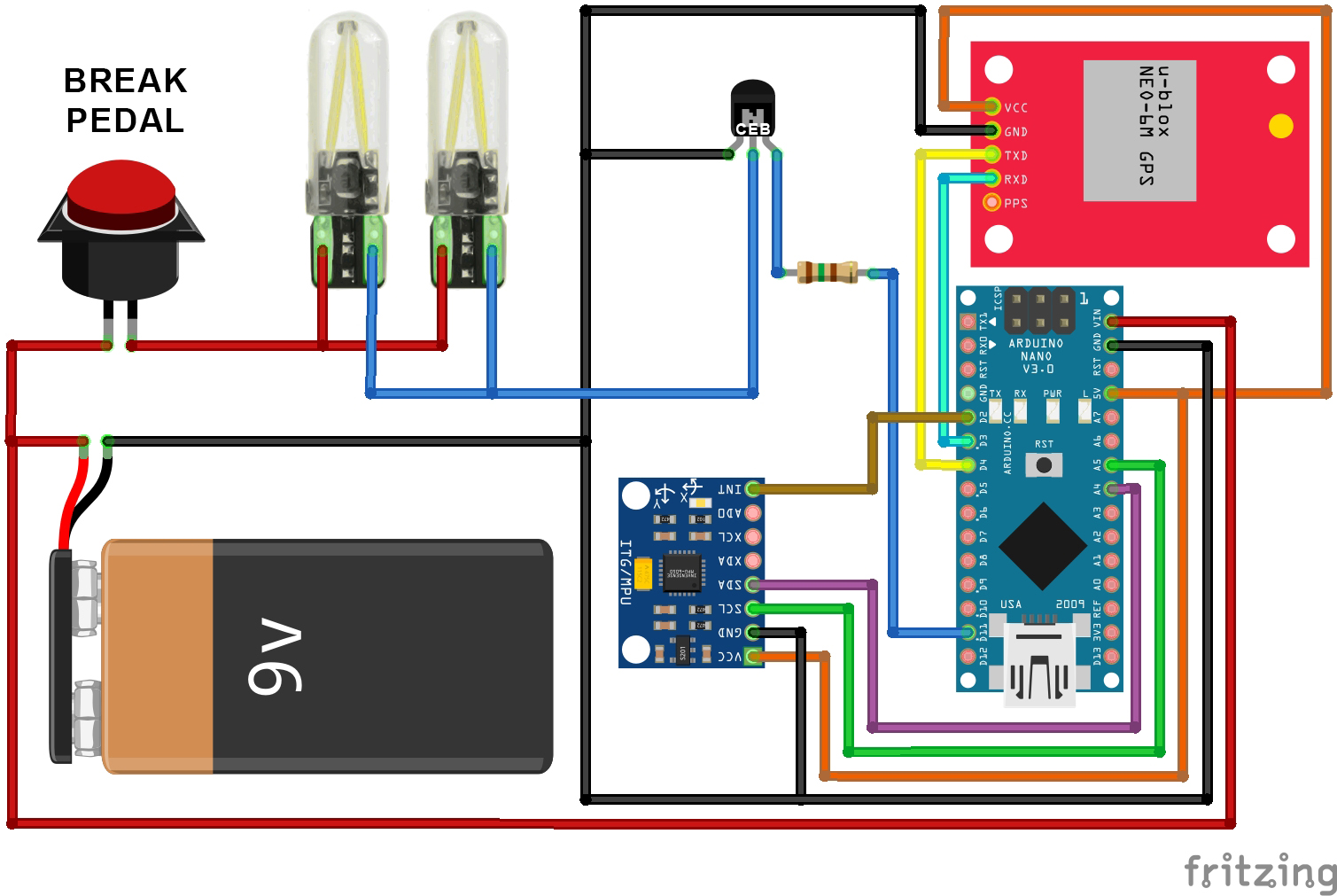
-
 1
1
-
-
Ai folosit cumva Coailii Antivirus?
tags:steaker,bucurii,botnetzi,hacer,email,parola1234-
1
-
-
as far as i remember din good old days puteai rescrie imei pe telefoanele Nokia Eseries/nSeries (e61,n95,n73 etc) cu NSS Tool.
sorry for revive -
Nokia 6650 Classic, no sarcasm around
")
edit: folosesc pla
-
1
-
-
-
NU au toate telefoanele cu android si play store Hangouts preinstalat!
Default doar la cele care vin cu Android Vanilla (adica nemodificat) ...deci Nexus si poate Pixel
-
1
-
-

-
6
-
-
Ai descoperit apa calda si mersul pe jos
Inainte sa postezi ceva, macar de curiozitate da un search pe forum-
5
-
 1
1
-
-
alea is doar adresele catre valori probabil.cardurile de ratb sunt cu NFC?
Si...suma de pe card nu e stocata cumva in baza de date a lor?Nu rpea are cum sa fie pe card.
Tind sa cred ca nu ai inteles cum functioneaza (posibil sa gresesc si eu) dar creditul de pe cartela e salvat in baza de date, iar tu cand validezi, cititorul se conecteaza la db si scade de acolo.
-
On 7/3/2016 at 7:40 PM, Sadiq said:
Am luat un MSi GP72 Leopard nou - £500, pretul in magazin ajunge aproape de £900
MacBook Pro 15 inch second hand - £550
Sunt foarte multumit de amandoua cu toate ca folosesc mai mult MSi-ul
Am uitat sa las reply cand le-am luat
Asa se face tati.Cand nu esti decis, le iei pe amandoua :)))
SI eu ma indrept spre un Macbook Retina 12.
edit 2020: m-am indreptat spre pla-
1
-
-
cumperi un d-ăsta și lipești un cablu jack de el daca nu vrei sa tai.
-
Stiu ca pe orange aseara n-a mers deloc 3g/4g....
Zvonurile sunt ca l-au lasat pe Dorel in camera serverelor si le-a scos din priza sa-si bage radioul
-
1
-
-
Congrats.Did you report it?
-
Bine-ai venit.Ce stii sa faci pana acum? Crezi ca esti peste media prietenilor/colegilor cand vine vorba de IT?
Also, las-o mai usor cu emoticoanele.
-
nu mai face double post, ai buton de edit.
sdcard se refera la sptiul intern.E o partitie. Nu se refera la microsd
Pui acolo romul.zip , in rootul folderului (acolo unde vezi folderele Android/Download/etc)DIn recovery dai "apply update from storage / sdcard"
-
1
-
-
de partea cealalta a p**ii :)))

-
1
-
-
-
Intai documenteaza-te despre procedee de printare pe plastic ca sa poti cauta dupa cu ce le scoti fara sa deteriorezi plasticul
-
Welcome aboard! Bafta si scapa de support
-
Scrie *#0*# si reseteaza/recalibreaza senzorii
-
1
-
-
Vand vest? Telekom/RDS.Schimb cu ?unc? afumat? :>
Ai pe youtube tutorial cu ce gasesti prin kali
-
Ai incercat sa rescrii firmware?se incalzeste tare cand il bagi la incarcat?

NTT Data Romania Data Breach
in Stiri securitate
Posted · Edited by LLegoLLaS
Long story short: (Breachsense)
Meanwhile pe tor-site-ul Ransomhub (neverificat) timerul e resetat la 23h desi in articolul initial era la 3zile
Data Breach Report
Victim 	nttdata.ro
Threat Actor 	Ransomhub
Date Discovered 	Jul 02, 2024
Description 	NTT Data Corporation is a Japanese multinational information technology service and consulting company headquartered in Tokyo.
Leak Size 	230GB
Newsarticle:
Japan's NTT Data says Romania unit suffered unauthorised access
Japan's NTT Data Group said on Wednesday its Romania unit was hit by an instance of unauthorised access in June.
The company is investigating how the access, which occurred on June 14, happened and whether information was leaked, a spokesperson said.
NTT Data said the access was detected on an old network that the Romanian unit was no longer using as its main network.
It had acquired all of the shares in a Romanian information technology service company in 2013 to make it a subsidiary.
Shares of NTT Data fell as much as 6.55% on Wednesday compared with a 1.26% gain in the benchmark Nikkei index.
sursa